COMPONENTS
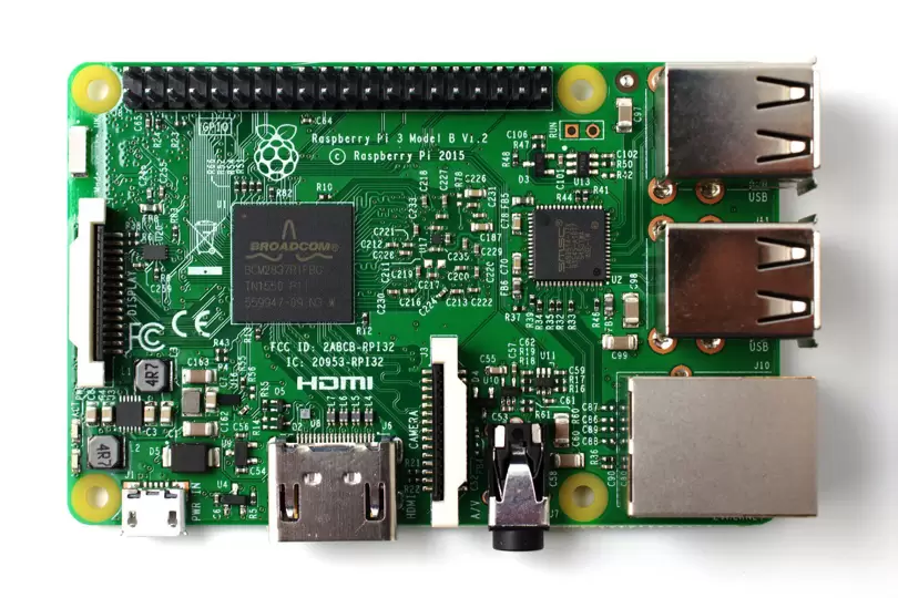
RASPBERRY PI 3_B ALL Components
Raspberry PI Model B Ports Specifications
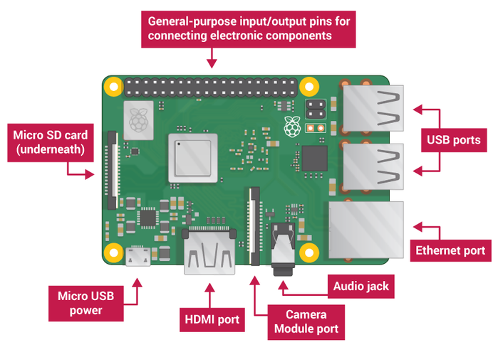
The Raspberry Pi has a number of ports which you will use to control the Raspberry Pi, and it can use to control other devices. Your Raspberry Pi will have the following ports:
USB – USB ports are used to connect a wide variety of components, most commonly a mouse and keyboard.
HDMI – The HDMI port outputs video and audio to your monitor.
Audio – The audio jack allows you to connect standard headphones and speakers.
Micro USB – The Micro USB port is only for power, do not connect anything else to this port. Always connect the power after you have already connected everything else.
GPIO – The GPIO ports allow the Raspberry Pi to control and take input from any electronic component.
SD card slot – The Raspberry Pi uses SD cards the same way a full-size computer uses a hard drive. The SD card provides the Raspberry Pi with internal memory, and stores the hard drive.
Specifications
CPU: Quad-core 64-bit ARM Cortex A53 clocked at 1.2 GHz
GPU: 400MHz VideoCore IV multimedia
Memory: 1GB LPDDR2-900 SDRAM (i.e. 900MHz)
USB ports: 4
Video outputs: HDMI, composite video (PAL and NTSC) via 3.5 mm jack
Network: 10/100Mbps Ethernet and 802.11n Wireless LAN
Peripherals: 17 GPIO plus specific functions, and HAT ID bus
Bluetooth: 4.1
Power source: 5 V via MicroUSB or GPIO header
Size: 85.60mm × 56.5mm
Weight: 45g (1.6 oz)
Micro-USB Power Supply
A 5V micro USB typically powers the Raspberry Pi. But how much current (in milliamps or amps) the Pi requires to function depends on your usage.
The recommended amount is between 700mA for a Raspberry Pi Model A, and up to 2.5A for a Raspberry Pi 3 Model B.
The Raspberry Pi boards typically draw much lower amounts, between 200 and 500mA.
Usage depends on what you’re doing with the Pi. Playing video and browsing the web draws more power than idling and booting. It also depends on what devices you have connected; some keyboards and mice draw more power than others.
SD Card Slot:
Secure Digital Card slot (SD Card) slot is a solid-state removable storage device which is required to run operating systems on Raspberry Pi as Raspberry Pi doesn’t have any onboard memory and data storage functionality. Raspberry Pi supports both SDHC (Secure Digital High Capacity) and SDXC (Secure Digital eXtended Capacity). The best suited card for proper running of all sorts of operating systems without any hiccup is Class 10 with speed @ 10MB/sec.
USB Ports & Ethernet Port:
USB Port: The number and type of USB ports on Raspberry Pi depends on the model. The Raspberry Pi Model B is equipped with two USB 2.0 ports; the B+, 2B, 3B and 3B+ have four USB 2.0 ports. The Pi 4 has two USB 2.0 ports and two USB 3.0 ports.
In all models prior to the Pi 4, the USB ports connect to a combo hub/Ethernet chip, which is itself a USB device connected to the single upstream USB port on BCM2835. On the Pi 4, the USB hub chip is connected to the SoC using a PCIe bus. On the Model A and Zero range, the single USB 2.0 port is directly wired to the SoC.
Ethernet Port: In order to enable Internet connection online and to update the software’s or to install latest packages from online repositories, Raspberry Pi supports Ethernet Connection. Raspberry Pi (Every Model) comprise of RJ45 Ethernet Jack which supports CAT5/6 cables. It enables Raspberry Pi to be connected to Wireless Router, ADSL Model or any other Internet connectivity sharing device.
HDMI (High Definition Multimedia Interface):
HDMI Port enables Raspberry Pi to be connected to HDTV via HDMI cable. Raspberry Pi supports maximum resolution of 1920x1200. With the help of HDMI Full HD MPEG-4 can be streamed via HDMI.
Video Out (RCA Cable):
In addition to HDMI Connectivity which facilitates HD connection, Raspberry Pi also has provision to be connected to standard monitor or TV using RCA video cable. RCA cable is less expensive as compared to HDMI but along with RCA cable, the user has to buy 3.5mm stereo cable for audio facilitation.
The Pi Model B+, Pi 2, Pi 3 and Pi 4 features a 4-pole 3.5mm audio jack which also includes the composite video signal. This has allowed for the removal of the composite video socket found on the original Model B.
The new jack is a 4-pole socket which carries both audio and video signals. It’s similar to sockets found on other multimedia devices such as iPods, MP3 players and smart-phones. It now used on the A+, B+, Pi 2, Pi 3 and Pi 4.
Status Led’s:
Raspberry Pi comprise of 5 main LED’s performing the following functions:
I. ACT: (Color-Green): The main function of ACT LED is to show card status. Normally flashing during any SD Card activity performed by end user.
II. PWR: (Color-Red): The main function of PWR led is power. This led is continuously ON when raspberry Pi is switched on and keep on till switched off.
III. FDX: (Color-Orange): The main function of FDX led is full duplex. This Led is powered on when Ethernet connection is of Full Duplex type.
IV. LNK: (Color- Orange): The function performed by LNK led is Link. This LED is powered on when Ethernet connection is established and packet transfer starts taking place.
V. 100: (Color-Orange): The 100 Led objective is to show 100 Mbps connection. When any connection is established at Ethernet port, this LED only gets on when connection is of 100 Mbps speed and gets powered off when connection is at 10 Mbps.
GPIO (General Purpose Input Output):
GPIO facilitates connecting all sorts of peripheral devices to Raspberry Pi. Raspberry Pi has onboard GPIO with 40 pins, 26 of which are used as digital inputs or outputs. More importantly, 9 of the 14 new GPIO pins are dedicated inputs/outputs, it also facilitates the onboard UART, I2C, SPI Bus and still large amount of free GPIO pins are there for add-on attachments.
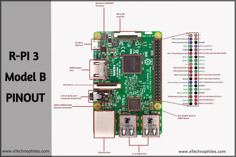
Raspberry Pi 3 GPIO Pinout / Pin diagram:
The Processor used in Raspberry Pi 3
Broadcom BCM2837: It is a 1.2GHz 64bit ARM quad-core Cortex A53 processor, with 512 KiB shared L2 cache, dual-core VideoCore IV GPU @ 400 MHz supporting OpenGL ES 2.0, hardware-accelerated OpenVG, and 1080p30 H.264 high-profile decode.
A powerful feature of the Raspberry Pi is the row of GPIO (general-purpose input/output) pins along the extreme right edge of the board. Like every Raspberry Pi chipset, it consists of a 40-pin GPIO. A standard interface for connecting a single-board computer or microprocessor to other devices is through General-Purpose Input/Output (GPIO) pins. GPIO pins do not have a specific function and can be customized using the software.
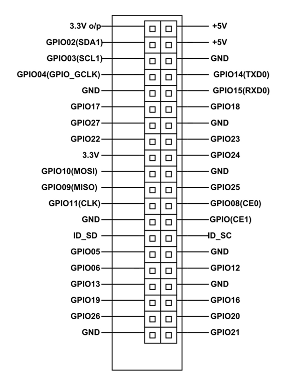
Raspberry Pi 3 Power Pins:
The board consists of two 5V pins, two 3V3 pins, and 9 ground pins (0V), which are unconfigurable.
5V: The 5v pins directly deliver the 5v supply coming from the mains adaptor. This pin can use to power up the Raspberry Pi, and it can also use to power up other 5v devices.
3.3V: The 3v pin is there to offer a stable 3.3v supply to power components and to test LEDs.
GND: Ground is commonly referred to as GND. All the voltages are measured with respect to the GND voltage.
Raspberry Pi 3 Input/Outputs pins:
A GPIO pin that is set as an input will allow a signal to be received by the Raspberry Pi that is sent by a device connected to this pin. A voltage between 1.8V and 3.3V will be read by the Raspberry Pi as HIGH and if the voltage is lower than 1.8V will be read as LOW.
A GPIO pin set as an output pin sends the voltage signal as high (3.3V) or low (0V). When this pin is set to HIGH, the voltage at the output is 3.3V and when set to LOW, the output voltage is 0V.
Along with the simple function of input and output pins, the GPIO pins can also perform a variety of alternative functions. Some specific pins are:
PWM (pulse-width modulation) pins:
Software PWM is available on all pins
Hardware PWM is available on these pins only: GPIO12, GPIO13, GPIO18, GPIO19
SPI pins:
SPI (Serial Peripheral Interface) is another protocol used for master-slave communication. It is used by the Raspberry pi board to quickly communicate between one or more peripheral devices. Data is synchronized using a clock (SCLK at GPIO11) from the master (RPi) and the data is sent from the Pi to our SPI device using the MOSI (Master Out Slave In) pin. If the SPI device needs to communicate back to Raspberry Pi, then it will send data back using the MISO (Master In Slave Out) pin. There are 5 pins involved in SPI communication:
GND: Connect all GND pins from all the slave components and the Raspberry Pi 3 board together.
SCLK: Clock of the SPI. Connect all SCLK pins together.
MOSI: It stands for Master Out Slave In. This pin is used to send data from the master to a slave.
MISO: It stands for Master In Slave Out. This pin is used to receive data from a slave to the master.
CE: It stands for Chip Enable. We need to connect one CE pin per slave (or peripheral devices) in our circuit. By default, we have two CE pins but we can configure more CE pins from the other available GPIO pins.
SPI pins on board:
SPI0: GPIO9 (MISO), GPIO10 (MOSI), GPIO11 (SCLK), GPIO8 (CE0), GPIO7 (CE1)
SPI1: GPIO19 (MISO), GPIO20 (MOSI), GPIO21 (SCLK), GPIO18 (CE0), GPIO17 (CE1), GPIO16 (CE2)
I2C pins:
2C is used by the Raspberry Pi board to communicate with devices that are compatible with Inter-Integrated Circuit (a low-speed two-wire serial communication protocol). This communication standard requires master-slave roles between both the devices. I2C has two connections: SDA (Serial Data) and SCL (Serial Clock). They work by sending data to and using the SDA connection, and the speed of data transfer is controlled via the SCL pin.
Data: (GPIO2), Clock (GPIO3)
EEPROM Data: (GPIO0), EEPROM Clock (GPIO1)
UART Pins:
Serial communication or the UART (Universal Asynchronous Receiver / Transmitter) pins provide a way to communicate between two microcontrollers or the computers. TX pin is used to transmit the serial data and RX pin is used to receive serial data coming from a different serial device.
TX (GPIO14)
RX (GPIO15)
CSI Camera Connector:
Raspberry Pi has a Mobile Industry Processor Interface (MIPI) Camera Serial Interface Type 2 (CSI-2). CSI-2 facilitates connection of small camera to Broadcom BCM 2835 processor. The function of this interface is to standardize the attachment of camera modules to the processors for the mobile phone industry. MIPI CSI-2 version 1.01 supports upto 4 data lanes, and each lane carries 1 Gbps bandwidth. The D- PHY specification defines the physical hardware layer interface between camera and processor to facilitate fast exchange of data.
System On Chip (SoC):
Raspberry Pi (System on Chip) SoC is ARM Based by Broadcom Technologies. The ARM processor runs from 700 Mhz to 1 Ghz. The SoC also facilitates videocore 4 GPU, and is capable for fast 3D core, openGL and supports Blueray and H.264 video playback.